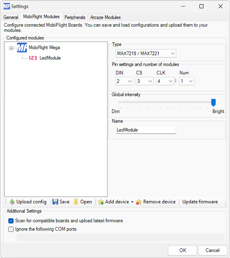
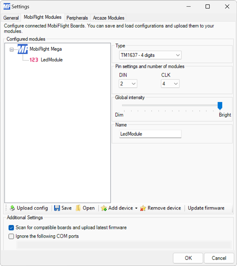
Settings reference

Settings reference

Modules dialog

Screenshot of the Modules dialog with the MAX7219 7-segment display configuration showing.
Setting Description
DIN The board pin connected to the DIN pin of the display. All digital and analog pins are supported.
CS The board pin connected to the CS pin of the display. All digital and analog pins are supported.
CLK The board pin connected to the CLK pin of the display. All digital and analog pins are supported.
Num The number of MAX7219 display drivers connected in series.
Global intensity The default brightness for the display.
Name The name for the display. Displayed in the output configuration dialog to identify the display when mapping the simulator output.
Screenshot of the Modules dialog with the TM1637 7-segment display configuration showing.
Setting Description
DIN The board pin connected to the DIN pin of the display. All digital and analog pins are supported.
CLK The board pin connected to the CLK pin of the display. All digital and analog pins are supported.
Global intensity The default brightness for the display.
Name The name for the display. Displayed in the output configuration dialog to identify the display when mapping the simulator output.

Tip

Changes to the Global intensity setting are not applied until uploaded to the board with the Upload config button.

Output display configuration

Screenshot of the Display tab with the Display Module type selected and configured to use display digits 1--6 with a decimal point at position 3.
Setting Description
Name The name of the 7-segment display to use, as defined in the Modules dialog.
Number For MAX7219 displays, selects which display in the chain to use. This option is not available for TM1637 displays.
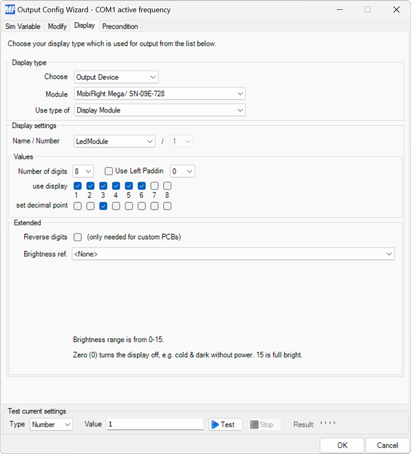
Number of digits Defines the number of digits connected to the driver chip. This option is obsolete and should always be left at the default value.
Use Left Padding When checked, inserts the selected symbol (either 0 or Space) in front of the displayed value to ensure the number of characters in the displayed value matches the number of checked use display digits.
use display Selects which digits on the display are used to display the value. Each checkbox corresponds to one digit on the display, from left to right.
set decimal point Selects which decimal point son the display are illuminated. Each checkbox corresponds to one decimal point on the display, from left to right.
Reverse digits When checked, reverses the order of the digits before sending to the display. This option is only required for custom PCBs where the displays were wired in reverse from the normal wiring order.
Brightness ref. Selects the config reference from the Modify tab to use as the brightness value for the display. The output value must be in the range 0–15, with 0 indicating off and 15 indicating full brightness.